


Search by shape, function & use


As electronic devices become smaller and more functional and powerful, there is a growing demand for high-precision resistors to achieve high precision in electronic circuits.
High-Precision Resistors are resistors whose resistance values do not vary much during the manufacturing process and whose resistance values do not fluctuate much depending on the operating environment. These resistors play an important role especially in circuits that require highly accurate measurement and control. The characteristics, applications and main series of High-Precision Resistors are explained in an easy-to-understand manner below.

The first point to be explained is resistance tolerance. There is variation in the resistance value of actual resistors. Therefore, during the manufacturing stage, they are manufactured to match a specific resistance value using methods such as trimming*1. Resistance tolerance indicates, in percentage, how much the resistance value of the manufactured resistor may deviate from the specific resistance value.
For example, if the resistance tolerance is ±1%, the resistance value of a resistor with a specific resistance value of 100Ω will be between 99Ω and 101Ω.
Most resistors widely available on the market have a tolerance of 5%.
However, high-precision resistors usually have a tolerance of less than ±0.1%, and ultra-precision resistors (RNCF series) can achieve a tolerance of ±0.01%, allowing resistance values very close to the designed resistance. This ensures stable circuit performance and accurate operation.
※1 Trimming is the process of cutting grooves into the resistor body to precisely adjust the resistance value.

The temperature coefficient of resistance indicates “how much the resistance value changes with respect to temperature changes in a resistor.” It is expressed in parts per million (ppm) as the change in resistance value per 1℃of temperature difference. The unit is ppm/℃.
It is a widely known parameter because it appears in resistor catalogs.
It is often called “TCR” from the initials of the English “Temperature Coefficient of Resistance”.
The range of a typical resistor is 10ppm/℃ to 1000ppm/℃.
(There are also high-precision products with a range of 1 to 5ppm/℃.)
Figure 1 below shows the possible range of resistance change for a product with ±100ppm/℃ when 25℃ is used as the reference temperature.
Depending on whether the TCR value is positive (+) or negative (-), the change in response to temperature will either increase or decrease.
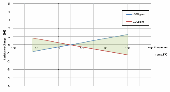
Figure 1 Resistance change range of ±100ppm/℃
Naturally, the smaller the TCR, the more stable the component characteristics are, enabling highly reliable circuit design.
Some products have multiple TCR grades in the lineup within a single product series, but generally the narrower the TCR range, the higher the cost, so it is recommended to select a product with a good balance.
An ideal resistor has only resistance components, but in reality, it has parasitic components other than resistance. A resistor body with electrodes on both ends and trimming lines on its surface serves as “capacitance”. Furthermore, lead wires, spiral trimming lines and wire-windings act as “inductance”. A simplified equivalent circuit diagram is shown in Figure 2. The impedance Z is expressed by the following formula.
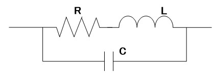
Figure 2 Simplified equivalent circuit of a resistor

In high-frequency circuits or current/voltage waveforms that contain high-frequency components, impedance may deviate from the nominal resistance value, which may affect circuit operation.
Figure 3 shows the frequency characteristics of a resistor. For resistors of 1MΩ or more, impedance may begin to change just before 100kHz, which is the switching frequency used in switching power supplies. Also, when the resistance value is low, parasitic inductance dominates in the high-frequency range, resulting in high impedance, and when the resistance value is high, parasitic capacitance dominates in the high-frequency range, resulting in low impedance.
With the trend towards higher frequencies in circuits, this is likely to become an issue that cannot be ignored.
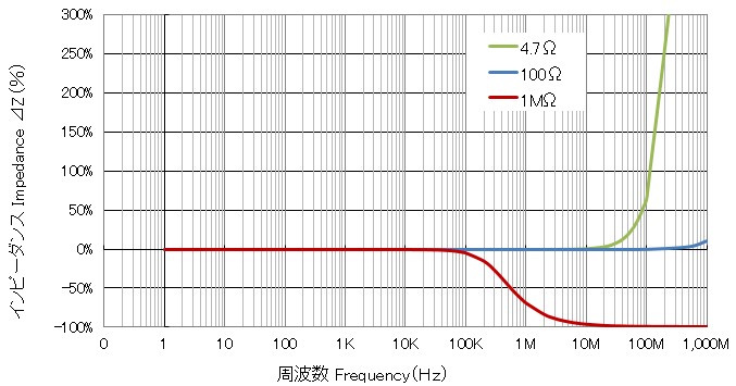
Figure 3 Frequency characteristics of a 1/4W resistor with lead-wires (simulation)
Generally, resistor noise is expressed by the following formula.
Resistor noise = Thermal noise + Current noise
The effective noise voltage of thermal noise is expressed by the following formula, which is determined by temperature, resistance value, and band, so there is no difference depending on the material.

Current noise is noise generated by the flow of electric current, and appears in the low frequency range. Therefore, in applications that handle low frequency minute signals (e.g. photodetection circuits and electrocardiograms), current noise is the main cause of degradation of the signal-to-noise ratio (S/N ratio).
This current noise depends on the material and structure. Figure 4 is a graph showing the difference in current noise due to the resistive film of a resistor with lead-wires. As the graph shows, metal film resistors have smaller current noise than carbon film resistors and metal oxide film resistors.
Metal film resistors with low current noise are suitable for applications that handle low-frequency, minute signals (e.g., photodetection circuits and electrocardiographs).

Figure 4 Difference in current noise due to resistive film (1kΩ)
It is known that the resistance value of resistors gradually changes over time.
For resistors with lead-wires, metal film resistors have a smaller change in resistance over time than carbon film resistors, making them suitable for circuits that require high reliability.
For chip-type resistors, thin film chip resistors have the advantage of being more stable over the long term than thick film resistors.
Figure 5 is a graph comparing the resistance tolerance, TCR (temperature coefficient of resistance), and durability performance of thin film chip resistors <RNCF series> and thick film chip resistors <CR series>. As this graph shows, thin film chip resistors can maintain stable performance over the long term.
From a long-term perspective, choosing highly reliable components such as thin film chip resistors and metal film resistors can improve the stability and performance of the entire circuit.

Figure 5 Difference in total tolerance
As mentioned above, when selecting a resistor, it is important to choose the appropriate type according to the application and the required reliability.
Below are some typical examples of the use of precision/high-accuracy resistors.
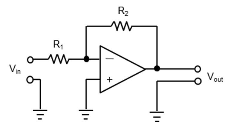
An operational amplifier is a circuit that amplifies minute signals, and the amplification factor (gain) of a non-inverting amplifier circuit like the one shown below is determined by the ratio of two resistors. Therefore, by using resistors with small resistance tolerances and temperature coefficients of resistance, the amplification factor (gain) can be set accurately.
Examples of application: sensor modules, measuring instruments, medical equipment
Recommended products: RNCF, CRU, RN/RNM, RNS
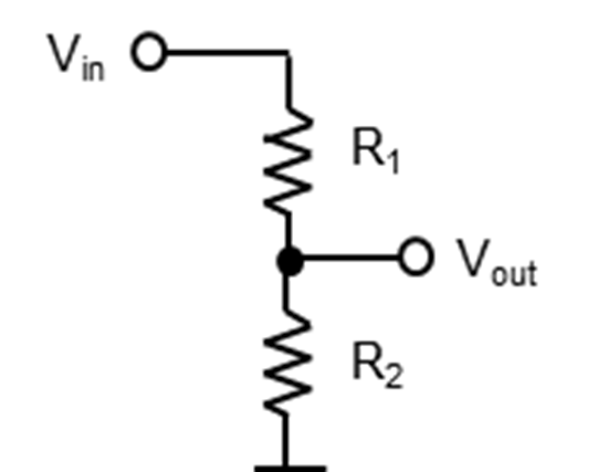
A voltage divider circuit is a circuit that divides the voltage across resistors by connecting resistors in series. This allows the input voltage to be adjusted to the desired value. Since the tolerance and temperature coefficient of the resistors directly affect the divided voltage, high-accuracy resistors are required.
Examples of application: power supply circuits, power measurement circuits, reference voltage generation circuits
Recommended products: RNCF, CRU, RN/RNM, RNS
It is used in combination with a sensor (thermocouple or resistance thermometer) to detect minute signals with high precision. This allows for accurate measurements.
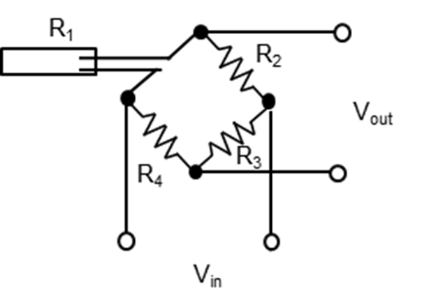
Examples of application: strain gauges, pressure sensors, temperature sensors
Recommended products: RNCF, CRU, RN/RNM, RNS
Used as shunt resistors when precise current measurement is required. For example, they play an important role in precision power supplies and motor current sensing.

Examples of application: power supplies, DC-DC converters, motor drive circuits, BMS
Recommended products: APS,CSS/CSSH,CSRF,CSR/CSRN,CBR
For more information on current measurement, please refer to the column ” Feature, Usage, and Trend of Current Sensing Resistors & Shunt Resistors.”
⇒Click here https://www.akaneohm.com/english/column/current-sense/
Below are the main series of precision/high-accuracy resistors.
[1] Ultra-precision grade
Precision Thin Film Chip Resistor <RNCF series>
https://www.akaneohm.com/products-data-eng/rncf/
[2] Precision grade
Precision Thick Film Chip Resistors <CRU series>
https://www.akaneohm.com/products-data-eng/cru/
[3] High power type
High Power Precision Thin Film Chip Resistors <RNTP series>
https://www.akaneohm.com/products-data-eng/rntp-e/
[4] Non-magnetic type
Non Magnetic Thick Film Chip Resistors <CRNM series>
https://www.akaneohm.com/products-data-eng/crnm/
[5] Electro-corrosion resistant
Moisture resistant Precision Thin Film Chip Resistor <RNCS/RNCH series>
https://www.akaneohm.com/products-data-eng/rncs-rnch/
[6] Current sensing
High Current Shunt Resistors <APS series>
https://www.akaneohm.com/products-data-eng/aps-e/
Ultra Precision Current Sensing Chip Resistors <CSS/CSSH series>
https://www.akaneohm.com/products-data-eng/css-cssh/
Foil on Ceramic Current Sensing Chip Resistors <CSRF series>
https://www.akaneohm.com/products-data-eng/csrf/
[7] Lead-wire-type precision grade
Metal Film Fixed Resistors <RN/RNM series>
https://www.akaneohm.com/products-data-eng/rn-rnm/
[8] Lead-wire-type ultra-small metal film
Flameproof Ultra Small Metal Film Resistors <RNS series>
https://www.akaneohm.com/products-data-eng/rns/
[9] Cement-type current sensing
Current Sensing Blade Resistors <CBR series>
https://www.akaneohm.com/products-data-eng/cbr/
<Note>
The above contents may change without notice.
Please check the latest information before making your decision. →Click here to contact us. https://www.akaneohm.com/english/contact/
– – – – – – – – – – – – – – – – – – – – – – – – – – – – – – – – – – – – – – – – – – – – –
