


Search by shape, function & use


■”Even though you made a prototype of the circuit, but the operation became abnormal.” In such a situation, why not review the characteristics of the resistors?
“A prototype circuit based on the design doesn’t work as expected, and the voltage and current values aren’t as calculated,” In that case, you have to review each part.
“What about the resistor? The resistance value is as calculated, so there’s no problem!” You may make this decision, but we recommend double-checking before doing so.
Perhaps parameters other than the resistance value may have an effect.
Three parameters of resistors that affect circuit operation are introduced and explained below.
■Temperature Coefficient of Resistance (T.C.R.)
The meaning of “temperature coefficient of resistance” is “how much the resistance value changes with the temperature change of the resistor”. TCR expresses the resistance change in parts-per-million (ppm) when the temperature changes by 1 degree. The unit is ppm/℃.
Many people are familiar with this parameter because it appears in resistor catalogs.
It is often called “TCR” from the initials of Temperature Coefficient of Resistance.
Resistance tolerance and rate of change are often expressed in %, so it is difficult to get a sense of the numerical value if expressed in ppm.
Remembering any of “10000ppm = 1%”, “1000ppm = 0.1%”, or “100ppm = 0.01%” will make TCR calculation easier.
Typical resistor TCR ranges from 10ppm/℃ to 1000ppm/℃.
(There are also high accuracy products with the TCR of 1 to 5ppm/℃.)
The Figure 1 below shows the resistance change range of ±100ppm/℃ products with 25℃ as the standard.
Depending on whether the TCR value is positive (+) or negative (-), the change in response to temperature will be either “increase” or “decrease.”
In addition, the TCR value has differences for each LOT and individual differences.
Figure 1 Resistance change range of TCR±100ppm/℃
As a matter of course, the smaller the TCR, the more stable the characteristics of the parts, which makes it possible to design highly reliable circuits.
Some lineup of products have multiple TCR grades within a single product series.
Basically, the smaller the TCR, the higher the cost, so it is recommended to select a product considering the balance between performance and cost.
■Voltage coefficient of Resistance (VCR)
The meaning of VCR is “how much the resistance value changes with respect to the voltage applied to the resistor”. The change in resistance value per 1V of voltage difference is expressed in percentage (%) or parts-per-million (ppm).
The units are %/V and ppm/V.
It is sometimes called “VCR”, taking the initials of Voltage Coefficient of Resistance.
Since the effect of VCR is small in general circuits/resistors, VCR is rarely described in catalogs or data sheets.
However, VCR is a parameter that should be considered when designing high voltage circuits and using high voltage type resistors.
Some of you may have read the above and started to have questions.
According to Ohm’s law (E=R*I), resistance R is a constant of proportionality between voltage and current.
If this law is true, then it is natural to raise the question that it is strange that the resistance value changes with the voltage.
In circuit design, the current and voltage are calculated and parts are selected based on the assumption that the resistance R is constant.
However, if the resistance changes depending on the voltage, problems such as the circuit not working as intended may occur. The VCR of actual resistors is very small, and there are almost no cases where it affects general circuits. However, in reality, the resistance value may change due to the applied voltage.
The calculation and the Figure 2 below are typical VCR values and simulation results.
<Example>
If VCR = -0.0005%/V and applied voltage = 100V, resistance change is “0.0005%/V*100V = -0.05%”.
In other words, with this VCR value, even if the resistance is 100kΩ when no voltage is applied, it functions as 99.95kΩ when 100V is applied.
Figure 2 Resistance value change simulation by VCR
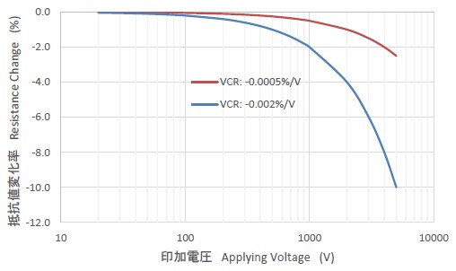
<Note> The resistance value change in the above graph is a phenomenon only while the voltage is being applied and does not mean that the resistance value changes permanently.
Depending on whether the VCR value is positive (+) or negative (-), the resistance change in response to the applied voltage will either increase or decrease.
The graph above is an example of negative (-).
As shown in the graph above, the higher the applied voltage, the larger the rate of resistance change.
Therefore, the effect of VCR is larger for high-resistance type or high-voltage type resistors with higher rated voltages. We perform measurements under the conditions of 0.01V to 200V depending on the resistance value range and product series.
If there is any doubt about the resistance value, we measure it according to JIS C5201-1 Section 4.5.
■Frequency characteristic
The circuit symbol for a resistor is R.
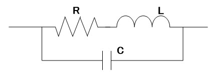
Ideally, a resistor should have only a resistive component as this symbol means, but in reality it has parasitic components other than resistance. There is capacitance in resistors between the two end electrodes or resistors with trimming grooves. Resistors with lead wires, spiral resistors, and wire-wound resistors have inductance. Based on these points, a simple equivalent circuit diagram of a resistor is shown in Figure 3 below.
Fig. 3 Simple equivalent circuit of resistor
In high-frequency circuits and current/voltage waveforms containing high-frequency components, the impedance may deviate from the nominal resistance value and this can affect the operation of the circuit.
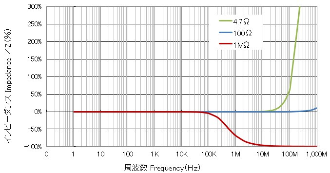
The Figure 4 below shows the frequency characteristics of a resistor. In particular, at 1 MΩ or more, the impedance may begin to change before reaching 100 kHz, which is used as the switching frequency in switching power supplies. In the trend of higher frequency circuits, frequency characteristics would become an important issue that cannot be ignored.
Figure 4 Frequency characteristics of 1/4W resistor with lead wires (simulation)