


Search by shape, function & use


1. Principle of resistance measurement – Ohm’s law –
Digital multi-meters are generally used to measure resistance. However,
digital multi-meters don’t measure “resistance itself”.
For example, in the Figure 1, when current I flows through resistance R,
voltage V is generated at both ends of resistance. (V is called “voltage drop”.)
At this time, a relationship of V = I x R is satisfied by Ohm’s law. Therefore,
as long as only I and V are known, R can be calculated by the transformed
formula R=V/I of Ohm’s law.
Digital multi-meters employ this principle of resistance measurement.
Digital multi-meterscalculate unknown resistance by measuring voltage
drop afterthe already-known current flows through the resistance.
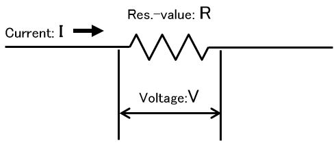
Ohm’s law: V=I×R
Figure 1 Concept of resistance measurement
2. Measuring method – 2-terminal method & 4-terminal method
The 2-terminal method and the 4-terminal method are general.
However, it is necessaryto adopt the 4-terminal method to measure low
resistance precisely. In the 2-terminal method, a resistor (Rx) and a measuring
instrument are connected with measuring cables as shown in Figure 2.
As these cables themselves have resistances (RL), the RLs would be a factor
of measurement error.
On the other hand, in the 4-treminal method, a resistor (Rx) and a measuring
instrument are connected with four cables as shown in Figure 3.
As the resistance of voltmeter is quite high, the current that flows from current
source doesn’t divertto the voltmeter but flow through Rx. Consequently the
RL resistances of the cables can be ignored.
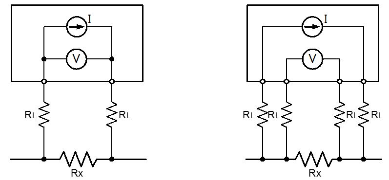
Figure 2 2-terminal method Figure 3 4-terminal method
3. Correct measuring procedure of 4-teminal method
As mentioned above, it is necessary to adopt the 4-terminal method to measure
low resistance. What is important in this section is that it is necessary to touch
measuring object with 4 terminals. (Figure 4)
If you measure as in the Figure 5, resistances of probes and also contact
resistances between probe and measuring object are measured.
As contact resistance between metals happens to be as much several mega Ω
or several dozen mega Ω high, measuring of low resistance requires special care.
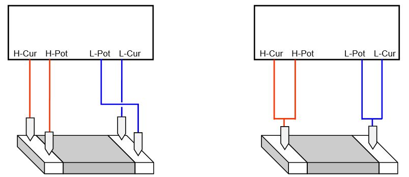
Figure 4 Correct 4-terminal method Figure 5 Wrong 4-teminal method
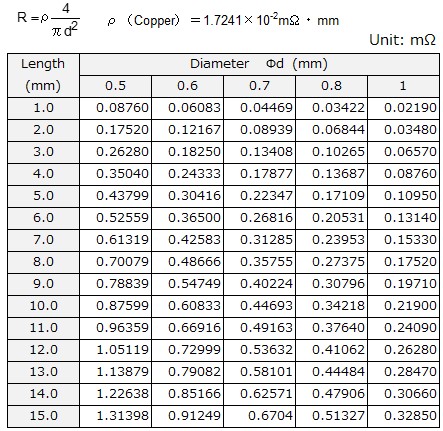
4. Error factor in measuring resistors with lead wires
4.1 Effect of measuring position
Resistance of lead wire is not zero, but it is as in Table 1. As in Figure 6,
measurement errormight occur depending on the measuring position.
Therefore, you should be careful when you measure resistance values and
design circuits so that these error factors willnot have negative effects.
Some makers define recommended measuring positions, so please check
catalog orcontact the maker in order to prevent troubles.
Tabel 1 Resistance Value of Copper wire
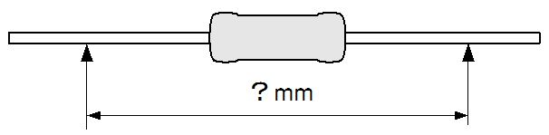
Figure 6 Error factor depending on measuring position
4.2 Effect of measuring clip
If measuring clip has some width as in Figure 7, there might be uncertainty in
measured value depending on that width.
It is best for you to use a point-contact-tool as much as possible.
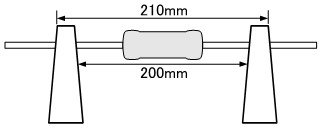
There is uncertainty for width of
10mm of the lead wire.
Figure 7 Error factor of clips
5. Error factor in measuring chip resistors
5.1 Effect of measuring position
Even though the same sample is measured, there might be errors depending on
positionsof chip resistor’s terminal where probes touch. This is because the
difference of length of current path depending on the measuring points would
affect resistance values. As some makers define recommended measuring
positions, please check catalog or contact the maker in order to prevent troubles.
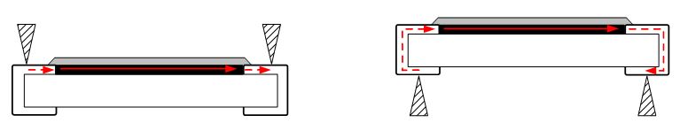
Figure 8 Touched on upper surface Figure 9 Touched on lower surface
5.2 Error caused by solder amount (fillet shape) at board mounting
Solder amount or fillet shape at the time of board mounting would affect resistance
values. This is because the resistance of the solder is inserted in series in the
resistor. (Figure 10).
It is recommended to check operations on the actual board not only catalog specs.
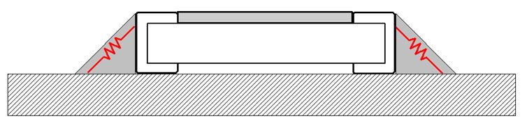
Figure 10 Error factor of solder
————————————————————————-
(c) Akahane Electronics Corp. 2016
→Click here to see the lineup of low resistance, current sensing, and shunt resistors.
→Click here to search quickly by power rating and resistance value.